


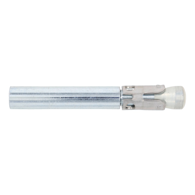

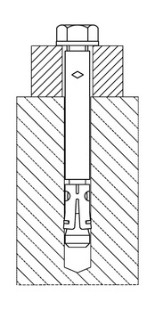
Fixanchor internal thread W-FAZ-IG/S - push-through installation
Fixanchor W-FAZ-IG in-place installation steel zp
ANC-(W-FAZ/S-IG)-(A2K)-20-M8X82
Art.-no. 0904708012
EAN 4048539763702


Register now and access more than 125,000 products
- High load-bearing capacity, low centre to centre and edge clearance
- Immediate load-bearing capacity – no waiting
- Torque-controlled expanding anchor made from galvanised steel
- Safe expansion in cracked concrete owing to fixing anchor cone with patented plastic coating
- Countersunk screws ensure an elegant appearance for visible anchorages combined with high load-bearing capacity (e.g. railings)
- ETA-99/0011 for individual attachment, option 1, cracked and non-cracked concrete
- Fire resistance: R30, R60, R90, R120; Technical Report TR020 (included in ETA-99/0011)
- The W-FAZ-IG fixing bolt anchor must be inserted using the appropriate approved setting tools (anchor system).
- Hexagonal bolts, countersunk screws, washers, countersunk washers and nuts have a special coating and are only permissible in the anchor system in accordance with ETA-99/0011. Therefore, please order separately.
- Threaded rods may only be used if the conditions specified in approval ETA-99/0011 (material quality, dimensions, mechanical properties) are met.
- The torque required for anchoring can be applied with Würth torque wrenches and suitable attachments (open-end socket spanners).
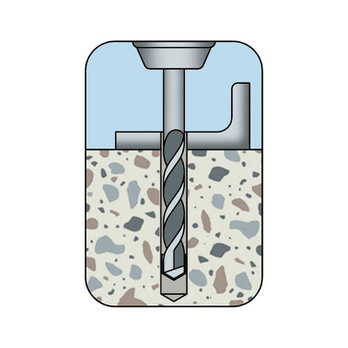
Create the drill hole
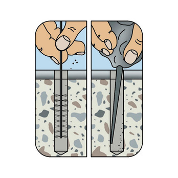
Clean the drill hole
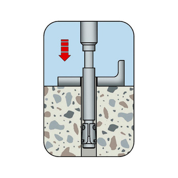
Knock in anchor with setting tool
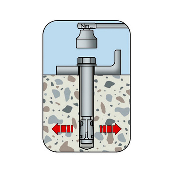
Apply torque
- ETA-99/0011 for individual attachment, option 1, cracked and non-cracked concrete
- Fire resistance: R30, R60, R90, R120; Technical Report TR020 (included in ETA-99/0011)
Datasheets(X)
CAD data (available after login)

Individual attachment with approval
Standard concrete C20/25 to C50/60 (cracked and non-cracked concrete)
E.g. metal structures, metal profiles, brackets, footplates, supports, cable conduits, pipes, railings, wooden structures, beams, stadium seating etc.
Individual attachment without approval
Can be used in concrete < C20/25 and compression-proof natural stone
May only be used in dry indoor areas
Metric anchor diameter | M8 |
Anchor length (l) | 82 mm |
Min. screw-in depth of threaded rod (Lsd) | 12 mm |
Material | Steel |
Surface | Zinc plated |
Nominal drill-bit diameter (d 0) | 10 mm |
Drill hole depth (h 1) | 75 mm |
Effective anchoring depth (h ef) | 58 mm |
| Performance data | ||||||
| Anchor diameter [mm] | M6 | M8 | M10 | M12 | ||
| Admissible centric tension load3) on an individual anchor without the influence of the edge distance | Tensile zone (cracked concrete C20/254), s ≥ 3 hef c ≥ 1.5 hef) | Nadm [kN] = C20/254) | 2,0 | 3,6 | 4,8 | 7,9 |
| Compressive zone (uncracked concrete C20/254), s ≥ 5 hef, c ≥ 2.5 hef | Nadm [kN] = C20/254) | 4,8 | 6,3 | 7,9 | 11,9 | |
| Admissible centric shear load3) on an individual anchor without the influence of the edge distance | Tensile zone and compressive zone (cracked and uncracked concrete C20/254) | Vadm [kN] = C20/254) | 2,9 | 4,3 | 6,2 | 13,9 |
| Admissible bending moment | Madm [Nm] | 20,6 | 30,4 | 43,4 | 118,3 | |
| Fire resistance rating Admissible load when exposed to fire (R30, R60, R90, R120) see European Technical Approval ETA-02/0017 | ||||||
| 3) The partial safety factors of the resistances regulated in the approval and a partial safety factor of the actions of γF = 1.4 have been taken into account. For information on combining tensile and shear loads and the influence of the edge distance and anchor groups, please refer to the European Technical Approval Guidelines (ETAG), Appendix C. 4) The concrete has normal reinforcement. Higher values are possible for higher concrete compressive strengths. | ||||||
| Anchor sizes
| |||||||||||||
| Anchor diameter W-FAZ-IG/S | [mm] | M6 | M8 | M10 | M12 | ||||||||
| Length of anchor | l [mm] | 60 | 70 | 80 | 72 | 82 | 92 | 80 | 90 | 100 | 96 | 106 | 116 |
| Maximum fixture thickness type S | tfix [mm] | 10 | 20 | 30 | 10 | 20 | 30 | 10 | 20 | 30 | 10 | 20 | 30 |
| Maximum fixture thickness type SK | 14 | 24 | 34 | 15 | 25 | 35 | 16 | 26 | 36 | 17 | 27 | 37 | |
| Characteristic values | |||||
| Minimum member thickness | d ≥ [mm] | 100 | 120 | 130 | 160 |
| Minimum spacing cracked concrete | smin ≥ [mm] | 50 | 60 | 70 | 80 |
| Minimum spacing uncracked concrete | 50 | 60 | 65 | 80 | |
| Minimum spacing cracked concrete | for c ≥ [mm] | 60 | 80 | 100 | 120 |
| Minimum spacing uncracked concrete | 80 | 100 | 120 | 160 | |
| Minimum edge distance cracked concrete | cmin ≥ [mm] | 50 | 60 | 70 | 80 |
| Minimum edge distance uncracked concrete | 50 | 60 | 70 | 100 | |
| Minimum edge distance cracked concrete | for s ≥ [mm] | 75 | 100 | 100 | 120 |
| Minimum edge distance uncracked concrete | 115 | 155 | 170 | 210 | |
| Torque while installing anchor type S | Tinst [Nm] | 10 | 30 | 30 | 55 |
| Torque while installing anchor type SK | 10 | 25 | 40 | 50 | |
| Torque while installing anchor type B | 8 | 25 | 30 | 45 | |
| Through hole in the attachment | df ≥ [mm] | 9 | 12 | 14 | 18 |
Last viewed

Tripod, stainless steel, air-cushioned for wide-area lights

Countersunk washer/washer A1 stainless steel

Universal holder E 6.3 (1/4") with quick-change chuck

Compressor oil WK 100

Marking tape, magnetic

1/4 INCH EXTENSION

Suction bell

Adapter For plug-in tools Plus to Max

Wedge lock washer W.TEC, narrow shape

Plastic barrier post with base for barrier chains